Wednesday, May 11, 2016
Final Report
Here is our final report.
https://drive.google.com/file/d/0B-ALWZulnBsEa1VrS2doSjh3Tlk/view?usp=sharing
https://drive.google.com/file/d/0B-ALWZulnBsEa1VrS2doSjh3Tlk/view?usp=sharing
Thursday, May 5, 2016
Fixing Baseline Issues
With the final demo coming up, we really needed to solve the random issues that we encountered before the baseline demo. After extensively digging around, I found out that the reason the display was very slow when using my laptop was because the serial USB connection that we were using the communicate with the mbed was being limited to 12mb/s (USB 1.0 speeds). The USB ports on the Pi, on the other hand, were running at 480mb/s (expected USB 2.0). This was likely because of a driver issue, but we were able to solve the problem by sending less data over serial so the port wouldn't clog up and slow down.
The other issue we had to fix was libfreenect rarely recognizing Kinect on the Pi. After 11 hours (!!) of researching and debugging, I found a post by someone who was having similar issues that said he noticed that the Kinect camera would disappear in the output of the `lsusb` command when libfreenect was trying to connect. So, I tried it myself. I ran `watch -n0 lsusb` (this runs lsusb on a loop) in one terminal window before running my Python code. Surprisingly, this actually just fixed the problem!
I'm still not sure what was/is going on, but running `watch -n0 lsusb` before using libfreenect seems to keep it working every time consistently.
Thursday, April 28, 2016
PCB Design
One of the more important things to do between demo days was the development of a PCB that could house all of our circuitry. With 32 motors and LEDs planned for the final product, condensing everything was very important in order to make a display that not only looks nice, but that does not take up unnecessary space with ugly wires.

Tuesday, April 26, 2016
Baseline Demo Day
Today we had our baseline demo and it went as really well! Many people liked our project, including Rahul, Sid, and Parth.
We had a little bit of a panic before our actual demo because after setting everything up with my laptop, the display was reacting incredible slowly, and we still have no idea what was going on. We ended up having to use the Raspberry Pi, without testing stuff on the laptop because for some reason the display was much more reactive using the Pi. However, the Pi started acting up as well. The library we used to communicate with the Kinect, libfreenect, suddenly wouldn't connect with the Kinect and would throw an error that none of the suggestions solutions could solve. After repeatedly killing the program and retrying, we finally got it to run and didn't touch it for the remainder of the demo day.
This is something that really needs to be looked at before the final demo, these kinds of issues shouldn't be happening.
After our demo we talked to Rahul about our reach goals. We decided on the following reach goals:
- Bigger display (6 x 4)
- Audio Interaction
- PCB
- More advanced hand tracking (incorporate more depth)
Monday, April 25, 2016
Almost Final form
Here's a nice clip showing off our almost fully completed project (created automatically by Google Photos):
https://goo.gl/photos/SyYrKWrHZT31GpRS8
https://goo.gl/photos/SyYrKWrHZT31GpRS8
Organizing Wires
Here is the display pre-consolidation:


Note that the servo wires are not attached in this picture. That's another 48 wires to add to that heaping cloud of copper.
Here is the result after soldering many connections together and organizing the (now connected) servo wires.
Sunday, April 24, 2016
Mass Production
After working with our 3 cubes for a few days and working the kinks out of our algorithms, we were ready to make the rest of the necessary cubes. This post is dedicated to pictures and information about that process.
Laser cutting:


Assembly:


Laser cutting:


After many hours of manufacturing, assembly, finding issues, disassembly, more manufacturing, more assembly, etc, our project assumed its final form (laptop for scale):

Saturday, April 23, 2016
Attaching lighting
With all the flickering issues gone, it was time to solder the LEDs to longer wires and attach them to the boxes. Using red as Power, black as Gnd, and white as Din/Dout, this is what a few of the LEDs looked like:

After attaching them to the central rod of each box, this is what we were left with:

After attaching them to the central rod of each box, this is what we were left with:
Through the magical use of electrical tape and hot glue, we managed to get each of them attached, while hiding the ugly wires from view.
Friday, April 22, 2016
Further LED issue
The video in the last LED post is not of the greatest quality, but the LEDs were flickering a noticeable amount. Given that we did not know the WS2812 in and out, we couldn't determine the root cause of this at first, but we googled and googled until we came up with..........nothing that worked. The only fix we found was to lower the voltage to 4.5 V from 5 V, but we had already done this earlier when the LEDs did not want to cooperate with us.
So, the magical fix is................a capacitor from power to ground. That was it. Flickering gone. Yay hardware.
So, the magical fix is................a capacitor from power to ground. That was it. Flickering gone. Yay hardware.
Hand Tracking Cubes
We were able to successfully combine the hand tracking from the Kinect with the 3 cubes we had constructed earlier. The tricky part of this integration was deciding on a protocol to communicate between the Raspberry Pi and the mbed. We ended up encoding the values into chars and sending that data over serial.
The other challenge was figuring out what cube should actuate based on hand position. We decided to split up the Kinect's depth camera's resolution into a grid based on the number of cubes we had (in our case 3x1). The algorithm from there was to determine which grid cell the user's hand was in (using the calculated centroid) and actuate the corresponding cube.
Here's a video of that working:
https://goo.gl/photos/t1Zf1Td3pkmxRz9JA
Multiple Cubes
We finally got the PWM Chip we ordered so we made more cubes to see if we could control multiple servos simultaneously. The PWM Chip has a fairly complicated control API and we had to resort to using a library someone made for the mbed to communicate with it. Unfortunately the library was poorly documented and figuring it out was a bigger headache than we wanted it to be. (If you're making a library, be sure to document it well!)
After we figured out the library, controlling the multiple servos was no problem for the mbed or the PWM Chip.
Here's a video of multiple cubes being controlled simultaneously:
https://goo.gl/photos/UQYwWZbLX12z3Pfy5
After we figured out the library, controlling the multiple servos was no problem for the mbed or the PWM Chip.
Here's a video of multiple cubes being controlled simultaneously:
https://goo.gl/photos/UQYwWZbLX12z3Pfy5
Thursday, April 21, 2016
LED pains
Once the LEDs finally arrived, it was time to figure out how to make them work. The data sheet available on the sparkfun website does not seem to be thorough at all, and upon further searches concerning the WS2812 chip inside, it doesn't even seem to be accurate. After searching for the correct data, using wait_us() to control the pulses did not seem to be accurate enough, so we resorted to using an mbed library. At first we used a Pololu library to control them, which seemed to work one night. However, when we tested them the next day everything simply failed, so we found a NeoPixel library that had less built-in functionality, but behaved as expected when we tested them. After testing a few basic colors and chaining them together, we implemented a rainbow design that went across a 4x4 grid of leds to finally get an attractive pattern going.
Here is a video of the result:
https://goo.gl/photos/eFYLkh8AxqiJxwu27
Here is a video of the result:
https://goo.gl/photos/eFYLkh8AxqiJxwu27
Wednesday, April 20, 2016
Hand Tracking Progress
We were able to get our hands on a Kinect v1 for the hand tracking portion of the project and it seemed to work pretty well!
That is, after an entire day (>8 hours!!) was spent installing libraries and getting both OpenCV and libfreenect working on the Pi.
Here's a demo of it working after all that time on a Raspberry Pi 3:
https://goo.gl/photos/fLYBDpTRrMvNqeDg8
The basic algorithm is as follows:
That is, after an entire day (>8 hours!!) was spent installing libraries and getting both OpenCV and libfreenect working on the Pi.
Here's a demo of it working after all that time on a Raspberry Pi 3:
https://goo.gl/photos/fLYBDpTRrMvNqeDg8
The basic algorithm is as follows:
- Get depth data from the Kinect depth sensor
- Filter the depth data so only objects a certain distance from the camera are even considered
- Find the contours of that data
- Calculate the moment of each contour and from that you can calculate the centroid
All of the computer vision was done using OpenCV, which provides functions to do the various steps.
Tuesday, April 19, 2016
LED decisions
Our original idea was to use RGB led strips for lighting of the project. This seemed like a step above normal LEDs because more colors could be used without an insane amount of wiring, while it was also easy to have many LEDs in the area without much added complexity. The main drawback, however, was that each LED could not be controlled individually. Rather, each strip could be controlled along the RGB spectrum, so we could have used several different strips to get different colors going at once. However, we found a more useful solution that would be much better suited to our project. Using individually addressable LEDs from sparkfun, we could not only control a full range of colors for each LED, but have the ability to move around each LED instead of confining it to a strip. The model we used is here: https://www.sparkfun.com/products/12877

Each LED has four pins - Din, Vdd, Gnd, and Dout. Din can connect to an mbed digital out pin, which controls the LED using a series of pulses. To control more than one at a time, the Dout on one light is simply connected to Din on the next one. Each LED is controlled by 24 bits, 8 for each color. This also allows for a very wide range of color choices, which will also be a good benefit for our design.
Thursday, April 14, 2016
First Working Prototype
We decided to scrap the cam design and instead use a Scotch yoke. This allowed us to have more control of the linear movement that the free floating design of the cam.
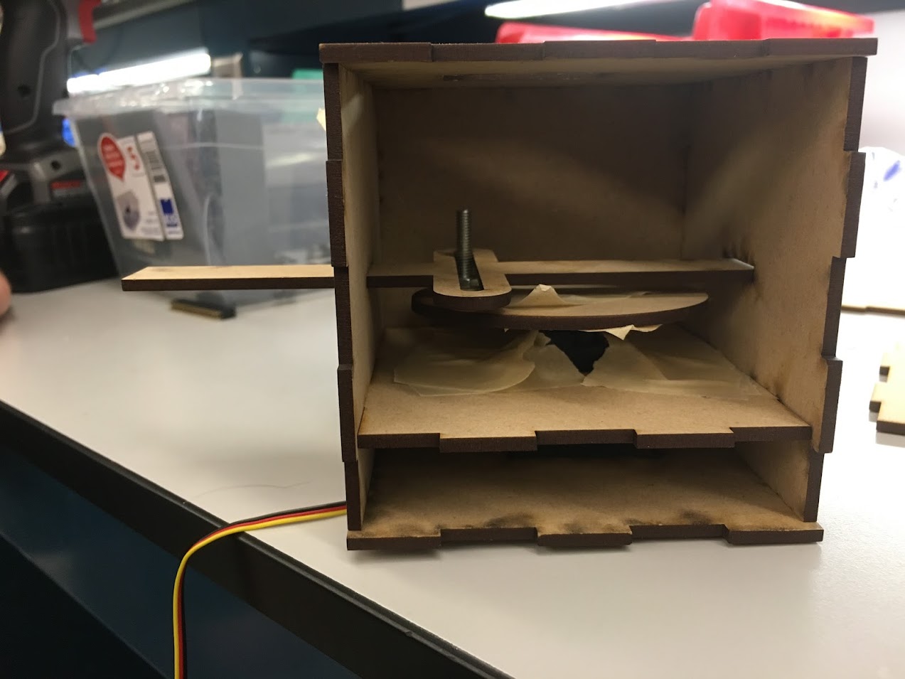
Here's a video of the system in action:
https://goo.gl/photos/zdu5MhSfUfc3X8Fx8
Here's a video of the system in action:
https://goo.gl/photos/zdu5MhSfUfc3X8Fx8
Tuesday, April 5, 2016
Project Proposal
- Project Title
- Hand Gestured 3D Pin Art
- Team
- Carter Rice
- Satya Bodduluri
- Motivation:
- Many forms of art today attempt to visualize the world that exists around us. Lighting systems exists that synchronize their colors to the music that is playing, while some displays mimic the motion of the user. The main concept behind 3D Pin Art is to take those two aspects as well as many other aspects of art and create a system that can demonstrate them. In a grid of pins that can be raised up and down, different musical patterns can be created, varying contours can be demonstrated, and even hand gestures can be implemented to take control of the surface. With 3D Pin Art, the user no longer has to make the final call between interaction and observation, but can experience both.
- Goal
- Create a flat gridded surface where each cell of the grid can be actuated upwards based on 2 kinds of inputs (2 modes)
- Audio
- Hand gestures
- Methodology
- Gridded Surface
- Use many mini servos with cams that will push rods connected to the tiles to actuate them upward

- Audio Input
- Break up audio of into different frequencies and actuate different sections of the board for different parts of the spectrum
- Hand Recognition
- Use a camera to detect position of hand and raise the section of the board that is underneath it
- Project Components
- Hardware
- Wiring for motors (H-bridges if needed)
- Relay system to switch between different positions on display
- PWM Chip to control the many servos (since servos need a constant PWM input to hold their position)
- Build an audio filter circuit to analyze different aspects of the audio signal
- Software
- Microcontroller
- Controlling the motors
- Interpret audio input
- Camera
- Detect hand position
- Mechanical
- Utilize cams to actuate the grid cells
- Create a rig that can hold all of our various components
- Deliverables
- Baseline:
- A fully working 3D Pin board
- Board will track hand and raise sections that are underneath it
- Add RGB Leds to the top of each pin that light up as the pin actuates
- Reach
- Use more advanced hand gestures to implement a holding pattern on display. Then sections of display can be raised up or down based on hand orientation
- Timeline
Week One: Create controllable pin using cam and micro servo, create control functions
Week Two: Compile version of pin array, begin design of audio filter and hand detection
Week Three: Integrate the mechanical and electronic parts together, i.e. finish baseline
Week Four: Implement reach goal
Subscribe to:
Comments (Atom)